This article is part of a multi-part series on how to identify, monitor, diagnose, and deal with harmonics in electrical power systems. Last month’s article discussed how to determine if current and/or voltage distortion levels were sufficiently high to classify a power quality issue as a harmonic problem. As outlined in prior articles, harmonics in electric power systems can cause negative issues, such as overheating and premature equipment failure. This month, we’ll review how to take the data gathered that measures harmonic levels to develop mitigation or reduction techniques for lowering total harmonic distortion (THD).
Isolation is a common means to locate “noisy” harmonic loads (e.g., VFDs, non-linear devices, etc.) away from sensitive loads that can be adversely affected. Electric utilities commonly install delta-wye power transformers for industrial customers because the delta-wye configuration has the advantage of preventing odd harmonic currents (i.e., 3rd, 5th, etc.) from transferring from the low-voltage wye side (customer) back to the electric utility grid where adjacent customers can be affected. Delta-wye transformers have a higher impedance to the flow of harmonic currents than to the fundamental current, creating effective isolation.
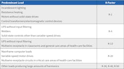
Within commercial and industrial facilities, K-factor transformers can be installed. These are designed to handle a higher degree of harmonic load currents without overheating, as compared to a standard transformer. The K-rating number of the transformer (i.e., 1, 4, 9, 13, 20) indicates the amount of harmonic current the transformer can handle. A K-factor of 1 indicates a linear load. A higher K-factor indicates increased heating from harmonics. For example, a circuit with a K-factor of 2 has twice the heating effect of a circuit with a K-factor of 1.
Guidelines have been developed that recommend a K-factor based on the predominant type of load in a circuit (see Table).
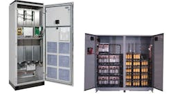
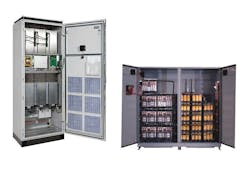
Isolation can also exist in the form of grouping harmonics on their own transformer, service, feeder, etc. If isolation of the noisy harmonic sources is not possible, practical, or ineffective, installing filters on the electrical power system is a possible means of mitigation. Filters come in many shapes and sizes, and can be either shunt or series, active or passive.
A shunt filter works by short-circuiting harmonic currents as close to the source of distortion as practical. This keeps the current out of the supply system. This is the most common type of filtering applied because of economics — and because it can also be used to correct power factor issues along with the harmonic current reduction.
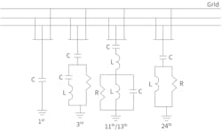
Series filters can also be used to block harmonic current. This is a parallel-tuned circuit that offers a high impedance to harmonic current. Power conditioners can use some form of series or shunt filters, which can be RLC (resistive, inductive and capacitive), LC, etc. The values of the components are designed to be tuned to the harmful harmonic frequency. See some examples in the Figure.
Typically, harmonic filters are either passive or active. Passive harmonic filters use inductors and capacitors to block harmonics or shunt them to ground. As frequency increases, the impedance of an inductor also increases, whereas the impedance of a capacitor decreases. Passive filters may become ineffective if harmonics change due to varying loads. In addition, multiple drives require multiple filters.
Along with filtering, several system design concepts can be used in the reduction of THD:
- Double the size of the neutral wire or separate the neutral for each phase.
- Full separate size insulated ground wire rather than relying on the conduit alone as a return ground path.
- Isolated ground wire for sensitive electronic equipment in a branch circuit.
- Oversize phase wires to minimize voltage drops on branch circuits.
- Shorten the distance on branch circuit from the power panel to minimize voltage drop.
Next month, we’ll look at a specific example of mitigation, and then discuss a new term related to harmonics in distributed generation applications (e.g., wind, solar, etc.). For background, read Part 1 of this series, “Harmonics: The Dreaded H Word.”
David Colombo, P.E. is a professional engineer located in Massachusetts, and the owner and principal of Power Engineers, LLC, a design, engineering, and consulting firm. He has more than 30 years in the electrical engineering and construction industry and is involved with the design of utility substation & distribution infrastructure, large-scale renewable energy projects, and commercial / industrial power systems. He specializes in the areas of medium-voltage design, power distribution, protection, metering, power quality, power studies, and arc flash analysis. He also provides owner’s engineering support for developers, EPC contractors, and project owners. Prior to starting Power Engineers, LLC and being an engineering consultant, he was a utility distribution supervising engineer. He holds a bachelor of science degree in electrical engineering from Worcester Polytechnic Institute (WPI) and a master of engineering degree in electric power engineering from Rensselaer Polytechnic Institute (RPI). He is a registered professional engineer in 13 states.
